


The images of the products are informative and may show minor differences, depending on the batch and the supplier. It is possible that the specifications and the price of the products can be changed without notice. We do our best to add the most accurate and correct specifications to the product page, but it is possible that they are not completely correct. if you identify such a case, please report this to us.
The product is intended for specialists and requires qualified and authorized personnel. The product does not include assembly/use instructions . Putting the product into operation by unqualified persons leads to the loss of the warranty according to the Terms and Conditions on the website.
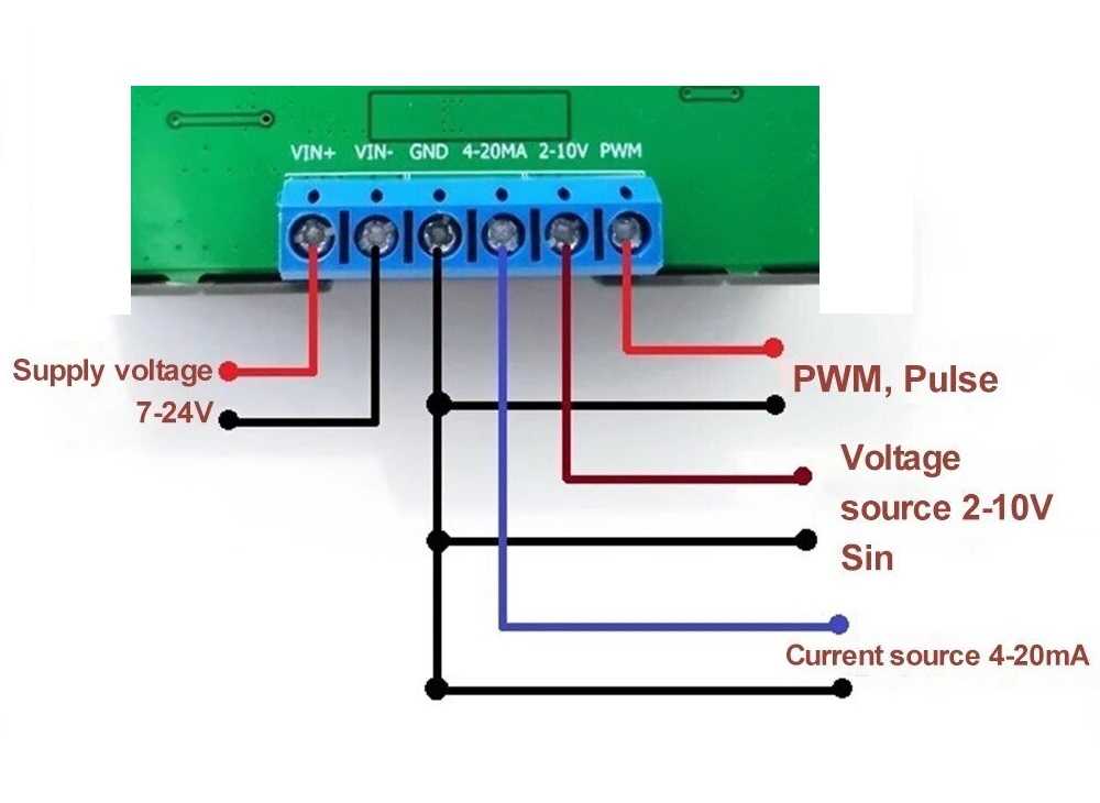
PWM signal generator module, panel, 2-10V, 4-20mA
 INTERNATIONAL DELIVERY
International fast shipping within EU. Free Shipping for orders above 100 EUR in most EU countries.
 FAST DISPATCH 24H
We ship from our stock within 24H
 DISCOUNT 5%
All orders minimum 100€
The WSFG-06 Signal Generator Module, designed to satisfy a varied range of requirements in testing and calibrating electronic and automation systems. Equipped with multifunctional capabilities, this adjustable signal generator is ideal for engineers, technicians and enthusiasts who require maximum flexibility and reliable performance.
The module supports multiple modes of operation: PWM mode for precise control of voltage, frequency and duty cycle. Pulse mode for detailed setting of timings and the number of pulses. Signal Source Module for providing a constant voltage or current source. Sine Wave Mode to generate frequencies in the 1-1000Hz range.
The signal loading capacity is strong and can deliver an output current of up to 30mA.
With a clear color display and an easy control panel layout, this signal generator is simple to operate even for new users.
Note: This product only produces the signal but CANNOT POWER the consumers DIRECTLY . The model is without RS485 communication (pins A and B are not usable).
Specifications:
Model: WSFG-06
Supply Voltage: 7-24VDC
Available Functions: PWM Mode, Pulse Mode, Signal Source Mode, Sine Wave Mode
Signal Load Capacity: Output current up to 30mA
Ambient Operating Temperature: -10-+70°C
Module dimensions: 79 x 43 x 41mm
Panel opening size: 76 x 39mm
Modes:
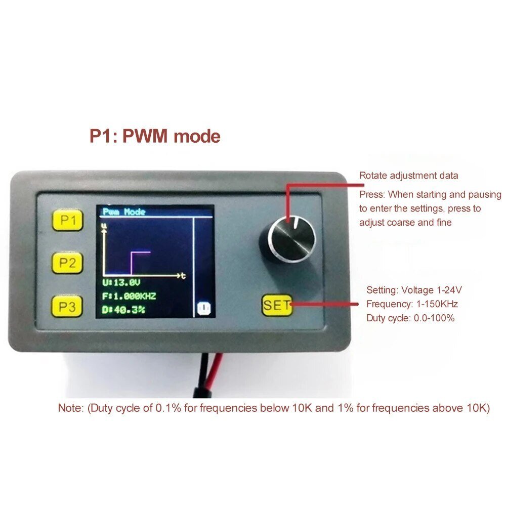
PWM mode:
Adjustable for: voltage, frequency, duty cycle
Accuracy: up to 0.1%
Voltage range: 1-24V
Frequency range: 1-150KHZ
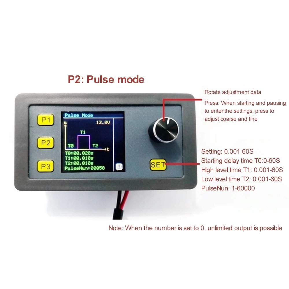
Pulse Mode:
Initial delay time T0: 0-60S
High level time T1: 0-60S
Low level time T2: 0-60S
The number of PulseNun pulses: 1-60000
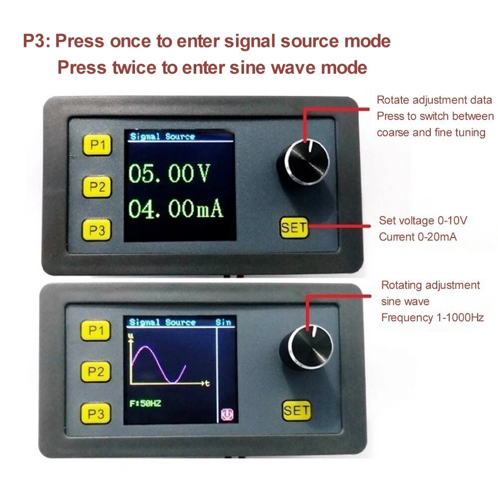
Signal Source Mode:
Voltage source: 2-10V
Current source: 4-20mA
Sine Wave Mode:
Frequency range: 1-1000Hz
Use:
Login:
Restoring Factory Settings:
In case of a power failure, press and hold the P1 button, then turn on the power and release the button to restore the factory settings.
Calibration function:
The signal source module offers calibration functions for voltage and current. For inaccurate displays, follow these steps: First, turn off the power, press and hold the coding switch while turning on the power to enter the voltage and current calibration mode. Use a multimeter to measure the output voltage (GND and 2-10V) or current (GND and 4-20mA), rotate to adjust the display to match that of the multimeter, press the coding switch to save, then turn off the power after three seconds. Accuracy can be calibrated to 0.1%!
PWM mode:
Press P1 once to enter, then press SET key to switch between setting voltage, frequency and duty cycle data in sequence (duty cycle can also be adjusted directly by rotating the encoder without entering SET mode). Turn the encoder to adjust the data (short press to switch between coarse and fine adjustment) and the signal is output in real time during the adjustment process. After adjusting the data, press the SET key to exit, and short press the encoder to enable or disable the output when exiting the SET state.
Pulse Mode PULSE:
Press P2 once to enter, press the SET key to switch between the set voltage, time T0 T1 T2 and the amount of pulses in the sequence. Turn the encoder to adjust the data (short press to switch between coarse and fine adjustment). During the adjustment process, the signal is emitted in real time. After adjusting the data, press the SET key to exit. When exiting the SET state, short press the encoder to enable or disable the output. Note: The voltage in pulse mode is the same as in PWM mode. When voltage adjustment is required, switch to PWM mode for adjustment.
Voltage and Current Signal Source Mode:
Press P3 once to enter, press the SET key to switch between the set voltage and current in sequence, and the signal starts to be output at the input. Turn the encoder to adjust the data (short press to switch between coarse and fine adjustment). During the adjustment process, the signal is emitted in real time. After adjusting the data, press the SET key to exit (Note: When it outputs between 4 and 20mA current, the load cannot have a resistance greater than 250 Ohms)
16 alte produse in aceeasi categorie:


Modul Dimmer touch cu control PWM


Driver PWM 5A, 90W, 3-35V


Modul generator DDS, AD9850, 0-40MHz, 3.3-5V


Customers who bought this product also bought:


PH Meter 0-14 probe with module

MicroSD module


Flux 10g, syringe, BST-559A

PCB ruler, 15cm


